![]()
AGA Geodimeter NASM-1
AGA Geodimeter NASM-2A
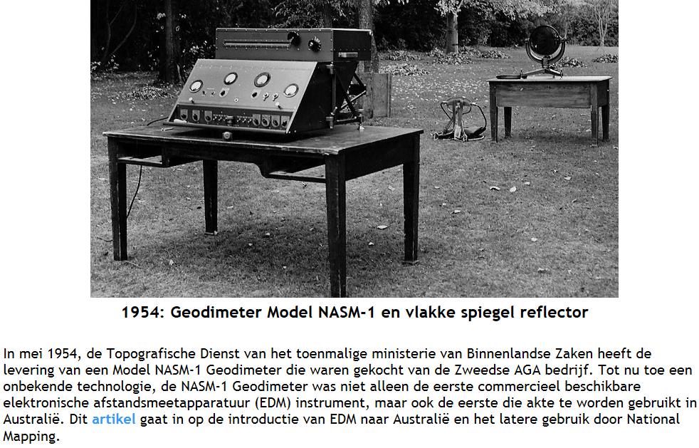
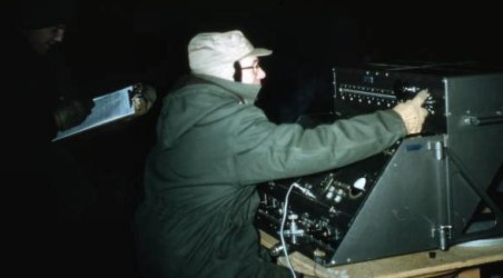
The light emitted by the NASM-1 was projected in pulses at 1/10,000,000 of a second (100 Nanoseconds) duration in groups of 100,000 or of 1/100 of a second duration. A delay of 500 Nanoseconds occurred between each group. Comparing the phase shift of the incoming signal to the outgoing signal provided the distance information. Ambient sunlight affected the reflected signal which degraded the accuracy of the measurement, making it necessary to take observations only at night. In fact Waller (1956) stated that during one night, measuring was delayed by moonlight swamping the reflected Geodimeter signal.
Geodimeter NASM-1
Problems with maintaining and monitoring a stable frequency electrical signal emerged with the adoption of the telephone and the evolution of broadcast radio. While investigating these problems in 1927, Canadian Warren Alvin Marrison developed a highly accurate clock. Marrison’s clock was based on the regular vibrations of a quartz crystal in an electrical circuit. Quartz clock operation is based on the piezoelectric (electricity resulting from pressure) property of quartz crystals. The interaction between mechanical stress and electric field of a quartz crystal in a suitable electronic circuit causes the crystal to vibrate and generate a constant frequency electric signal. This signal is then divided up electronically until the number of pulses reaches 60 per minute and the output fed to the (analogue and later digital) clock display.
While at the Nobel Institute of Physics in Stockholm, Sweden in the latter 1940s, Dr Erik Osten Bergstrand developed an instrument to measure the speed of light. At its heart was the ability to use a crystal to control the emitted light so that its behaviour was consistent. His first trials required an instrument at both ends of a line of known distance, but this was soon replaced by a single instrument and a mirror reflector. In 1947, Bergstrand took his instrument to a 7,734m baseline and obtained a measurement of 299,793.1 ±0.2 km per second for the speed of light. (Bergstrand’s value for the constant was very close to today’s value of 299,792,458 ±1.2 metres per second). In 1947 when he had a value for that constant, Bergstrand could adapt his device to obtain the distance between any two intervisible points. Bergstrand took his idea to AGA who built a prototype in 1951 and then produced the first commercial model of the Geodimeter, the NASM-1 in 1953. Thus EDM was born!
The light emitted by the NASM-1 was projected in pulses at 1/10,000,000 of a second (100 Nanoseconds) duration in groups of 100,000 or of 1/100 of a second duration. A delay of 500 Nanoseconds occurred between each group. Comparing the phase shift of the incoming signal to the outgoing signal provided the distance information. Ambient sunlight affected the reflected signal which degraded the accuracy of the measurement, making it necessary to take observations only at night. In fact Waller (1956) stated that during one night, measuring was delayed by moonlight swamping the reflected Geodimeter signal.
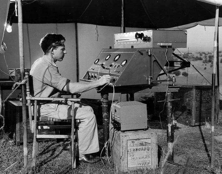
Geodimeter NASM-1 in Australia
The then Deputy Director of National Mapping, Bruce Lambert, saw the Geodimeter concept demonstrated at the International Union of Geodesy and Geophysics congress in Stockholm in 1948 (Lines, 1992). While Lambert had some initial concerns about the introduction of such electronically complex equipment into his organisation, these doubts were dispelled after discussion with Australian scientific experts.
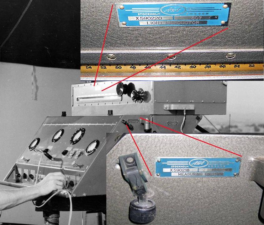
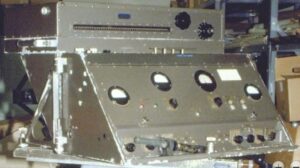
Photograph of assembled Measuring Unit and Light Conductor components of NASM-1 Geodimeter with enlarged identifying plates inset.
The production of the AGA NASM-1 was limited to ten units. Of these, American mapping organisations bought five of the ten instruments (Smithsonian, 2014) and most likely the South African’s one instrument (McLean, 2015). As the serial number of the Natmap unit was 7, AGA/Sweden probably kept unit 1 with units 2 to 6 going to the Americans and one of the remaining three units supplied to South Africa.
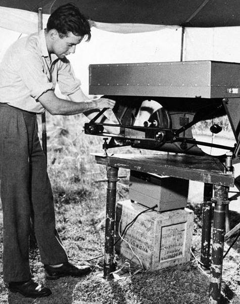
Soon after Natmap’s Geodimeter arrived in Australia, Natmap found that its successful deployment and use required several prerequisites. The measuring and optical units together weighed some 100kg, so the sites at which the measuring unit could be used required vehicle access. Transportation over Australian outback roads also needed to be considered. An International two wheel drive, 10 cwt panel van was obtained to meet these requirements. A Landrover with trailer acted as a support vehicle and carried the reflecting mirrors. For relatively short distances over rough or steep terrain for which the International was not designed, the Landrover could be pressed into service to carry the Geodimeter to the required site.
Nasm-2A
The NASM-2A was the first commercially available electro-optical distance meter. The Geodimeter (acronym for geodetic distance meter) was the invention of the Swedish Physicist Dr. Erik Bergstrand who designed and applied it to the measurement of the speed of light over known distances in 1947. Earlier versions of the NASM-2A include the NASM-1 and NASM-2 which were first put into practical use in 1953 and 1955 respectively.
 AGA Geodimeter NASM-2A
This Geodimeter NASM-2A is an electronic-optical instrument for first-order geodetic distance measuring purposes and is capable of measuring distances up to 50 km. The instrument consists physically of two units, the ‘measuring unit’, housing the electronic equipment, and the ‘optical unit’, containing the light conductor and the two large spherical mirrors. With the two units combined, the instrument weighs approximately 100 kg.
The first commercial instrument (Geodimeter NASM-2) was produced by the Swedish company AGA and became available in 1950. With the early Geodimeters, longer distances could only be measured at night.
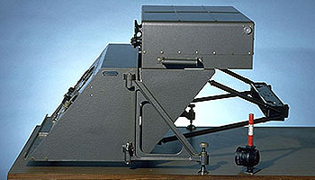
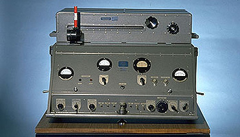
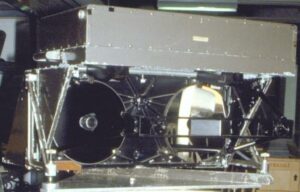
A circa 1959 AGA 2A assembled and showing the front control pane. Bottom: The AGA 2A from the side showing the separate measuring and optical units. Photos courtesy of the University of New South Wales School of Surveying and Spatial Information Systems Virtual Surveying Instrument Collection.
First produced in Sweden in 1953, the Geodimeter was based on the principle that a beam of light could be used to measure the distance from one point to another. The Geodimeter could be used to measure base lines with greater precision than previously possible and accomplish in hours what had previously taken weeks. The instrument worked by sending a light signal of known wavelength to a reflector. The wavelength of the returning signal was compared to the outgoing one, and the difference (called the “phase shift”) was measured. Using multiple frequences of light, the instrument computed a distance based on the known lengths and measured phase shifts of returning light waves. The Geodimeter was the first electronic distance measurement instrument to use visible light to measure distance.
The Coast and Geodetic Survey (C&GS) tested the various versions of Geodimeters rigorously as they became available. The Model 1, produced in 1953, was followed by Models 2 and 2A. Models 2 and 2A were similar to the Model 1, but had features that increased the Geodimeter’s measuring range. The “2A” model, shown here, included a measuring unit containing electrical systems and an optical unit containing a light conductor and two large mirrors.
Historic Reference
People have always been fascinated with the starry sky, developing astronomy from myths into science. The evolution of telescopes and more detailed observation of planets and stars led to attempts to determine the speed of light as well as increasingly refined instruments to measure this speed.
It was in pursuit of the value of the speed of light that a Swedish physicist named Erik Bergstrand began experimenting with a system that bounced known, carefully modulated wavelengths of light off of a reflector at a precisely measured distance. Since the time between the outgoing and return of the signal was so infinitesimally short that it could not be measured directly, a special instrument called an oscilloscope was used to measure light travel time.
Having used distances to determine the speed of light to his satisfaction, Bergstrand then proposed to reverse the process. In the late 1940s, he asked the company Svenska Aktiebolaget Gasaccumulator (AGA) to develop the first commercial geodetic distance meter, and thus development of the Geodimeter began.
The skeleton towers built in order to see over obstructions during a survey had evolved over the years from wood to a standard steel Bilby tower, named after its designer, Jasper Bilby. During observations, equipment plus crew perched on a small platform on top of the tower, sometimes over 100 feet high. Monroe Rivers, Geodetic Advisor for Kansas and veteran of CG&S Geodimeter surveys, said that when using the 2A, “not much room [was] left on [the] Bilby Tower for observer and recorder.”
In 1960, the Air Force asked the C&GS to determine the positions of missile tracking cameras around Cape Canaveral, Florida, with extremely high accuracy. A 2A was used to obtain results that far surpassed both the requirements and any accuracy ever obtained in an extensive geodetic network. The camera surveys were extended to other camera stations in Florida and Georgia, and then evolved into the Transcontinental Traverse, a continent-spanning, high-precision network of surveys that was completed in 1976.
This Geodimeter NASM-2A is an electronic-optical instrument for first-order geodetic distance measuring purposes and is capable of measuring distances up to 50 km. The instrument consists physically of two units, the ‘measuring unit’, housing the electronic equipment, and the ‘optical unit’, containing the light conductor and the two large spherical mirrors. With the two units combined, the instrument weighs approximately 100 kg.
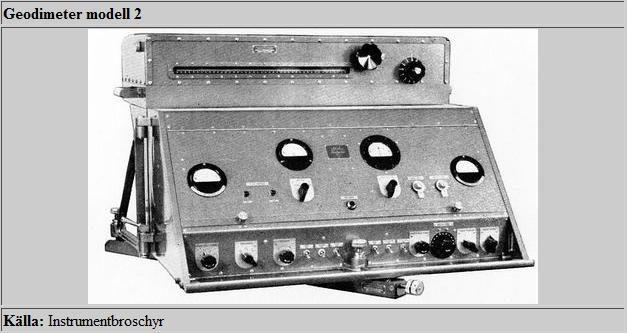
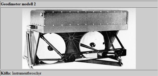
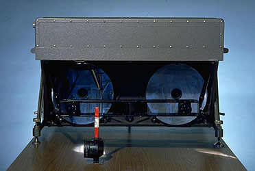
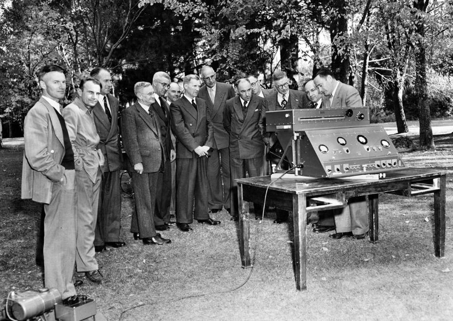
The first image above shows the front control panel view of the assembled instrument consisting of the two units. The second image shows the side view of the instrument, and here the two units can be clearly differentiated with the measuring unit on the left side of the image and the optical unit on the right. The third image represents a rear view of the Geodimeter (opposite side of control panel) where the two large “transmitting” and “receiving” spherical mirrors are clearly visible.
The mirror lenses with their focusing devices are mounted on a beam attached to the front of the optical unit by means of ball links. This makes the position of the complete optical system fixed with regard to the measuring unit and hence adjustments are reduced to a minimum. In order to protect the Aluminium coated glass surfaces of the mirrors they are covered with a very thin layer of silicium-monoxide.
The “electronic system” is mounted inside the measuring unit and contains the crystal oscillator with a power amplifier for the light modulator, the photo multiplier with associated circuits for detecting and indicating the zero points and the power supply that converts the mains voltage to the operating voltages for the electronic tubes. The purpose of the “optical system”, which is housed inside the optical unit, is to project the modulated light on the reflector and to concentrate the reflected light on the phototube. The built-in light conductor offers a possibility of an internal calibration of the instrument which considerably increases its precision.
The primary power required to run the Geodimeter is about 140 W, which is supplied by a 220 V petrol generator. The instrumental accuracy is primarily limited by the accuracy of the modulation frequency, as this directly determines the unit length. Experience has shown that after a few months running-in-time, the frequency error will be smaller than one part per million (1 ppm).
1956 : EDM: Geodimeter 2
The Geodimeter (acronym for geodetic distance meter) was the invention of the Swedish Physicist Dr. Erik Bergstrand and was first introduced in 1953. The Geodimeter was a light-based EDM. By measuring the time required for a beam of light to travel to a bank of retroreflective prisms and back, it could accurately determine the distance between the two points.
Geodimeter Model 2A
Geodimeter Model 2A
Bron; http://xnatmap.org